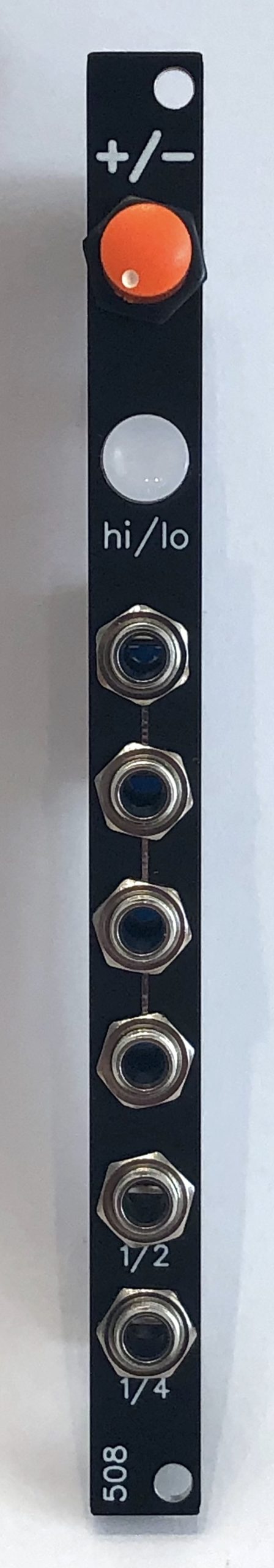
Range-switchable clock module that varies from ~1 Hz to ~12 Hz (actually down to 1/4 Hz thanks to the integral clock divider)
It has 4 outs of the main clock, plus 1 each of 1/2 and 1/4 clock division, designed to make it easy to do simple beats (or anything else requiring clock division) without needing a separate clock divider.
The pushbutton to change the range has a blinkenlight inside it.
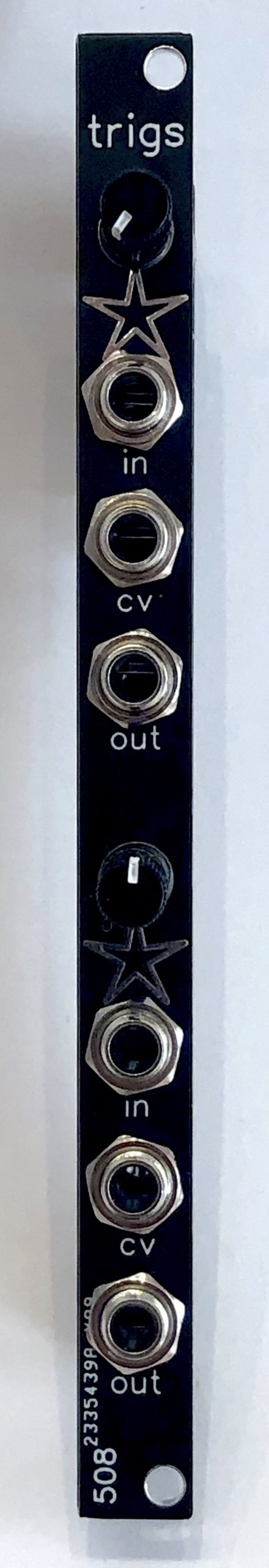
A lot of my percussion modules are expecting well-formed triggers, but clocks and other things typically put out gates. This is a dual gate-to-trigger conditioner — it will narrow just about any gate down to proper trigger width, but its output is also fully adjustable from 0ms up to the full width of the original gate. So you can use it if, for example, you’re using a clock divider that puts out double-length gates that you want to shape back down to the same width as the rest of the gates you’re using. Or anything else along those lines.
The trigger/gate width is fully CV controllable across the same range that the knob gives you.
The input of the top half is normalled to the input of the bottom half, in case you want 2 different lengths from the same gate input.
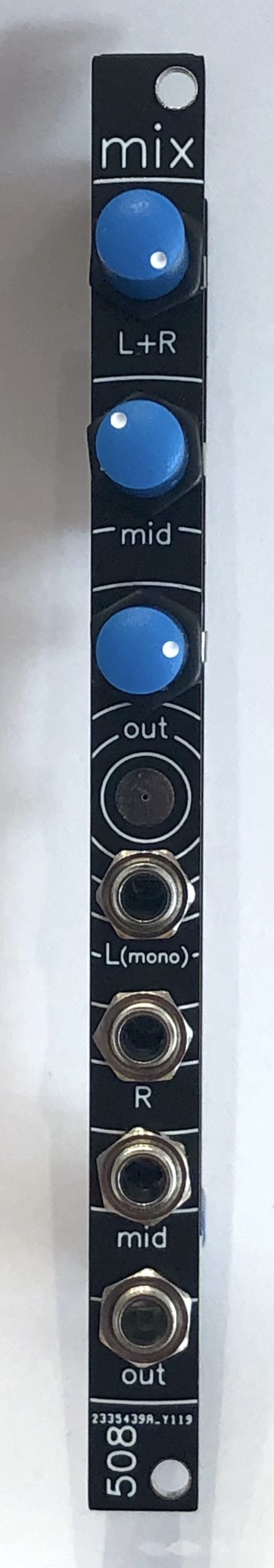
A simple stereo mixer — it has 1 plain-mono input, a second mono input that becomes a hard-panned left-channel when the third input, a dedicated right channel, is patched into. No pan pots, sorry, it’s 2HP. I actually designed it to go with a combination 4-way low-pass gate and stereo panning mixer that I haven’t gotten around to uploading here yet.
It has a reasonably decent headphone amplifier IC as its output stage, set to provide enough gain to drive my Sennheisers.
Seems like everyone has to design one of these sooner or later.
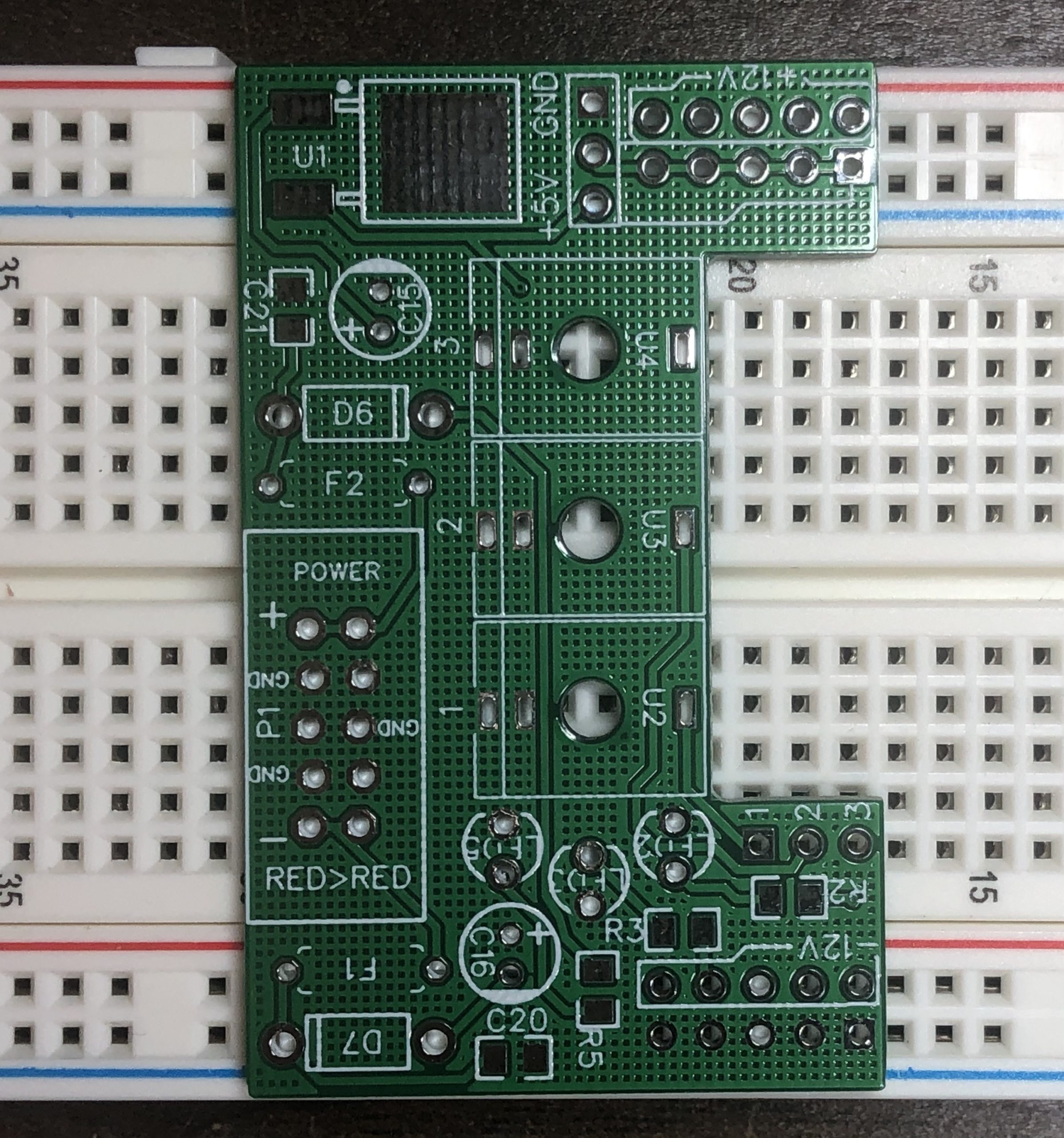
The jumper-able 5v/ground on one side is borrowed directly from Transient Modules.
My biggest peeve with Eurorack breadboarding is jacks — with pots, the Song Huei tall trimmers are easy to come by, cheap, and their legs fit breadboard holes pretty well. But jacks are a pain, so I went ahead & put three on here. The cutout on the board is to give you access to the rows where the jacks’ tip contacts come out. Sleeve & switch are both tied to ground for simplicity’s sake.
This is the ec500 error.core ONLY. You will most likely need the following accessories for this to be useful to you:
There is also an i/o expander which adds a lot of additional features. If you’re thinking of buying both, the bundle will be the easiest path.
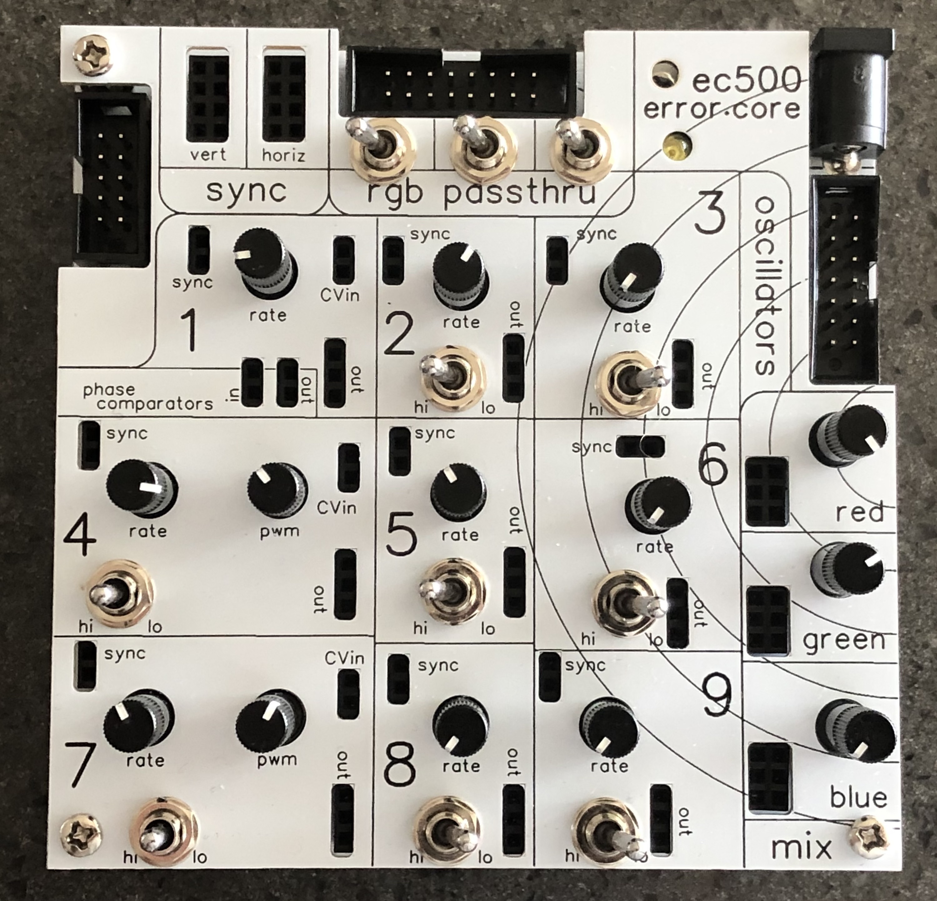
The error.core is the hub of the ec500 system – it takes 12V DC power, regulates it down to 5VDC, and provides an expansion bus that delivers power and hsync/vsync to expansion modules. It also has the connector where various interfaces – currently just VGA, others TBD – attach.
It has 9 oscillators, all of them square-wave. 6 are simple, not voltage-controllable, and provided by a single 40106 IC. 2 of them are provided by a 556 timer IC, and are voltage controllable with variable pulse-width. 1 is provided by the VCO in a 4046 PLL chip, which also provides a phase-comparison circuit. All of the oscillators are syncable, and 8 have switchable capacitors for speed control.
Beyond that, there are three mix busses (R, G, B), as well as switches to control whether RGB signals are passed thru from whatever external source is connected.
This is a KIT — PCB, panel, and all necessary parts to build the ec500 error.core. It is a fairly intricate build, including many surface-mount components, so we don’t recommend this to DIY newcomers. Build docs are in our github.
The error.core is the hub of the ec500 system – it takes 12V DC power, regulates it down to 5VDC, and provides an expansion bus that delivers power and hsync/vsync to expansion modules. It also has the connector where various interfaces – currently just VGA, others TBD – attach.
It has 9 oscillators, all of them square-wave. 6 are simple, not voltage-controllable, and provided by a single 40106 IC. 2 of them are provided by a 556 timer IC, and are voltage controllable with variable pulse-width. 1 is provided by the VCO in a 4046 PLL chip, which also provides a phase-comparison circuit. All of the oscillators are syncable, and 8 have switchable capacitors for speed control.
Beyond that, there are three mix busses (R, G, B), as well as switches to control whether RGB signals are passed thru from whatever external source is connected.
This is the ec500 error.core ONLY. You will most likely need the following accessories for this to be useful to you:
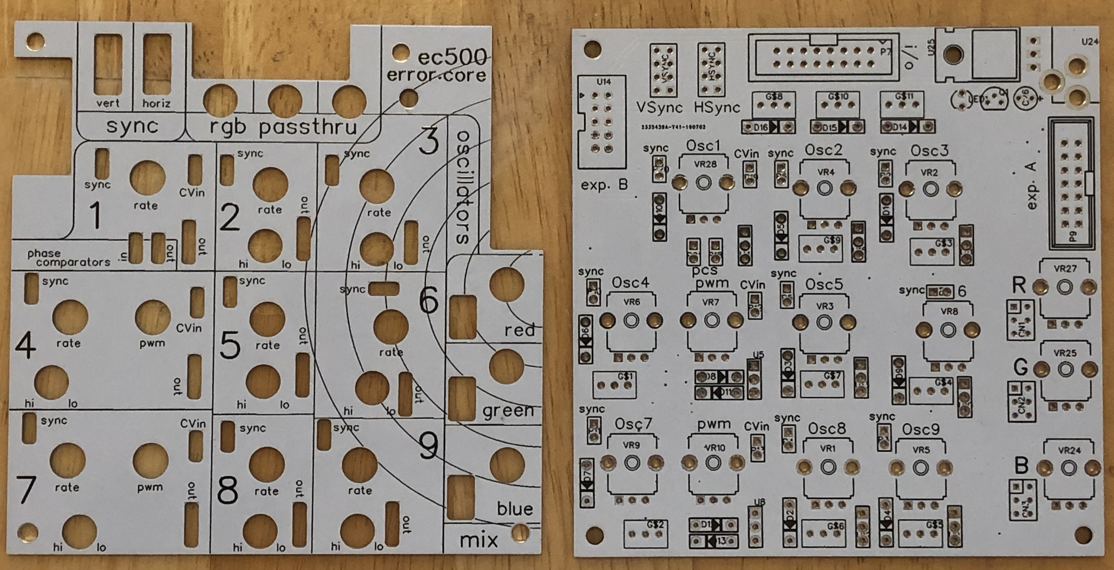
This is an option to purchase PCB + Panel ONLY. You will need to source all other parts yourself, and build it yourself. If you’re trying to buy a full kit, go here. If you’re trying to buy a prebuilt unit, go here. For the complete ec500 system, go here. Build docs are in our github.
The error.core is the hub of the ec500 system – it takes 12V DC power, regulates it down to 5VDC, and provides an expansion bus that delivers power and hsync/vsync to expansion modules. It also has the connector where various interfaces – currently just VGA, others TBD – attach.
It has 9 oscillators, all of them square-wave. 6 are simple, not voltage-controllable, and provided by a single 40106 IC. 2 of them are provided by a 556 timer IC, and are voltage controllable with variable pulse-width. 1 is provided by the VCO in a 4046 PLL chip, which also provides a phase-comparison circuit. All of the oscillators are syncable, and 8 have switchable capacitors for speed control.
Beyond that, there are three mix busses (R, G, B), as well as switches to control whether RGB signals are passed thru from whatever external source is connected.
This is a fully built ec500 i/o expander. NOTE: You MUST have an ec500 error.core for this to work!
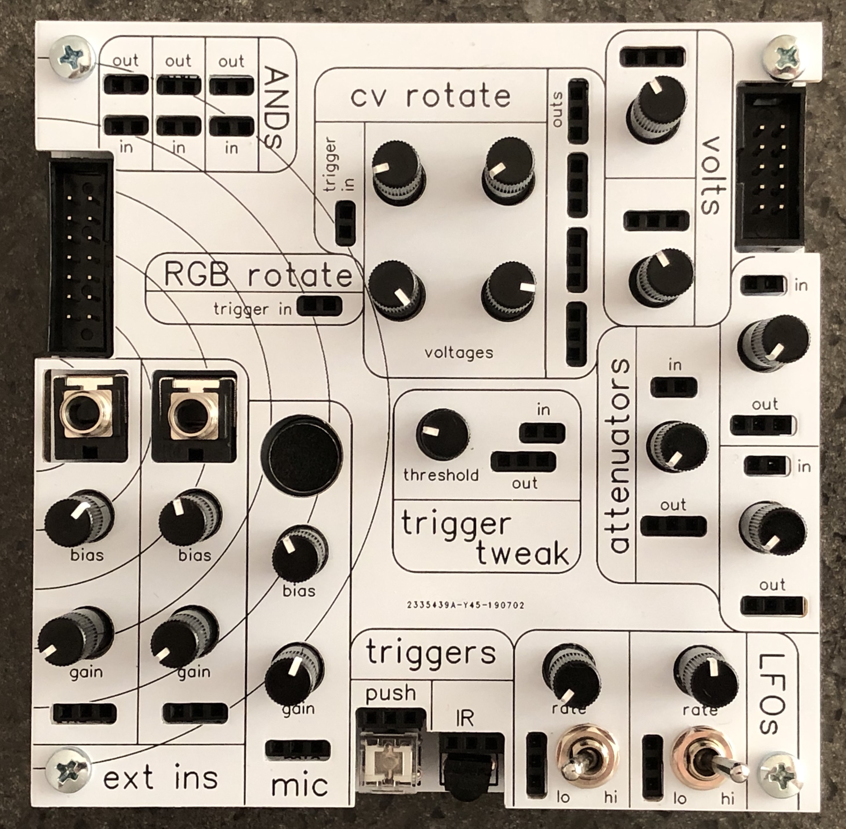
The ec500 i/o expander adds a number of new features to the error.core; it also depends on the error.core for power, so you will not be able to use it by itself. Among the features of the i/o expander are:
- Two line-level inputs with adjustable gain and DC offset
- An on-board microphone with adjustable gain and DC offset
- A lighted pushbutton switch
- An infrared receiver
- Two triangle-core LFOs with switchable range
- Three passive attenuators
- A comparator that is configured to condition triggers from other inputs, but which also has Other Uses
- A bunch of control voltage sources, some of which round-robin with suitable trigger input
- A triggerable round-robin for the main R, G, & B busses from the error.core
- Three AND logic gates
This is a KIT — PCB, panel, and all necessary parts to build the ec500 i/o expander. It is a fairly intricate build, including many surface-mount components, so we don’t recommend this to DIY newcomers. You will not be able to use this by itself; you will also need an ec500 error.core. Build docs are in our github.
The ec500 i/o expander adds a number of new features to the error.core; it also depends on the error.core for power, so you will not be able to use it by itself. Among the features of the i/o expander are:
- Two line-level inputs with adjustable gain and DC offset
- An on-board microphone with adjustable gain and DC offset
- A lighted pushbutton switch
- An infrared receiver
- Two triangle-core LFOs with switchable range
- Three passive attenuators
- A comparator that is configured to condition triggers from other inputs, but which also has Other Uses
- A bunch of control voltage sources, some of which round-robin with suitable trigger input
- A triggerable round-robin for the main R, G, & B busses from the error.core
- Three AND logic gates
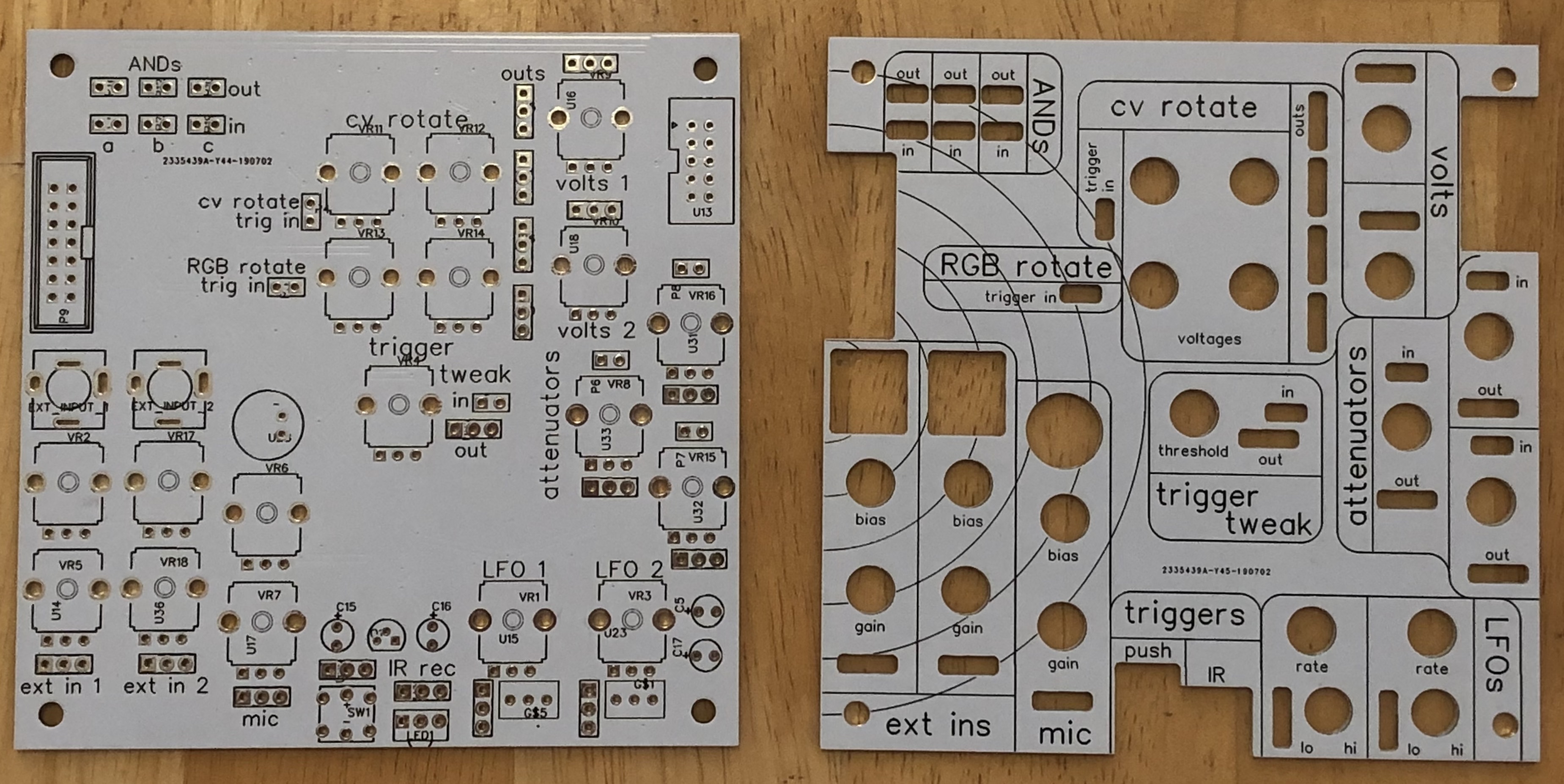
This is an option to purchase PCB + Panel ONLY. You will need to source all other parts yourself, and build it yourself. If you’re trying to buy a full kit, go here. If you’re trying to buy a prebuilt unit, go here. For the complete ec500 system, go here. Build docs are in our github.
The ec500 i/o expander adds a number of new features to the error.core; it also depends on the error.core for power, so you will not be able to use it by itself. You must have an ec500 error.core. Among the features of the i/o expander are:
- Two line-level inputs with adjustable gain and DC offset
- An on-board microphone with adjustable gain and DC offset
- A lighted pushbutton switch
- An infrared receiver
- Two triangle-core LFOs with switchable range
- Three passive attenuators
- A comparator that is configured to condition triggers from other inputs, but which also has Other Uses
- A bunch of control voltage sources, some of which round-robin with suitable trigger input
- A triggerable round-robin for the main R, G, & B busses from the error.core
- Three AND logic gates
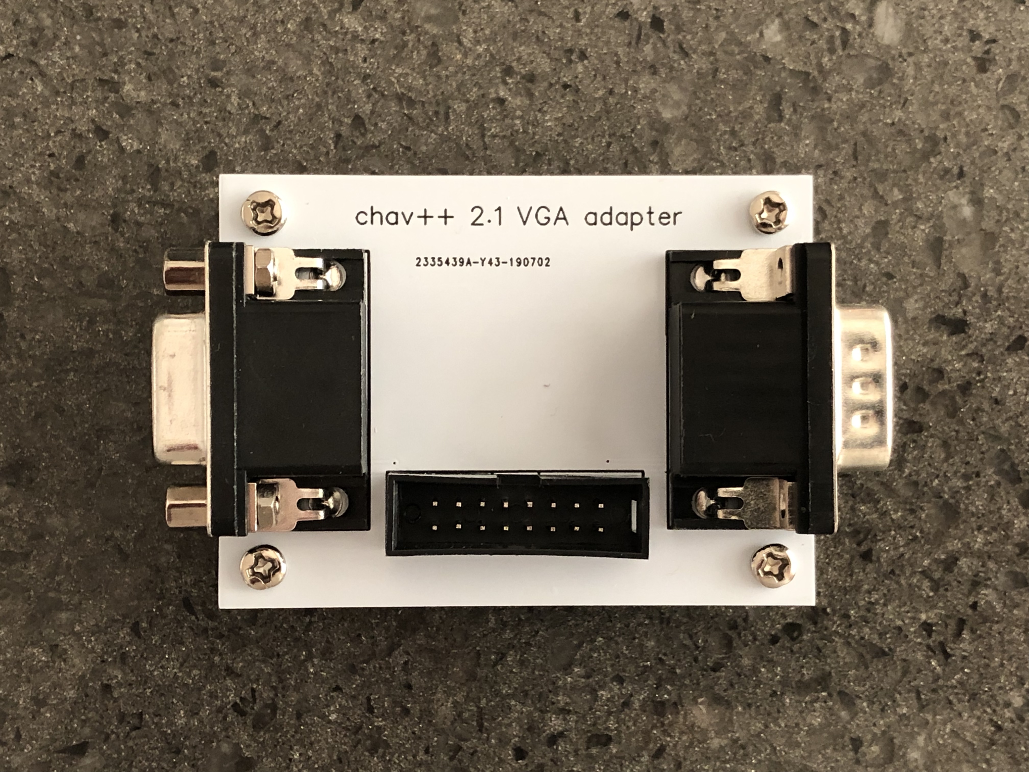
This VGA adapter is how you interface your VGA signal provider with the ec500 system. By default, we use the same little red $5 VGA tester that Jonas used in the original CHA/V, but you can theoretically use anything else that outputs a VGA signal, up to & including your laptop, which I do not recommend, for the sole reason that I do not make any promises about this not damaging your laptop. It shouldn’t, but I don’t want to be responsible if it does.
In essence, your VGA source plugs in to the right-hand side (w/the male pins), and your VGA display device plugs in to the left-hand side, and your ec500 error.core connects via the 16-pin ribbon cable in the center. That’s all there is to it. This adapter routes the necessary signals – R, G, B, hsync, vsync, ground – to the ec500, and then brings back whatever mangled RGB you generate with the ec500, sending it along to your display device.
Please note that this will do literally NOTHING without the ec500 error.core.
This is a kit that comes with all of the parts necessary to build the ec500 VGA adapter. You will have to build this yourself. It will take about 15 minutes. Build docs are in our github.
This VGA adapter is how you interface your VGA signal provider with the ec500 system. By default, we use the same little red $5 VGA tester that Jonas used in the original CHA/V, but you can theoretically use anything else that outputs a VGA signal, up to & including your laptop, which I do not recommend, for the sole reason that I do not make any promises about this not damaging your laptop.
In essence, your VGA source plugs in to the right-hand side (w/the male pins), and your VGA display device plugs in to the left-hand side, and your ec500 error.core connects via the 16-pin ribbon cable in the center. That’s all there is to it. This adapter routes the necessary signals – R, G, B, hsync, vsync, ground – to the ec500, and then brings back whatever mangled RGB you generate with the ec500, sending it along to your display device.
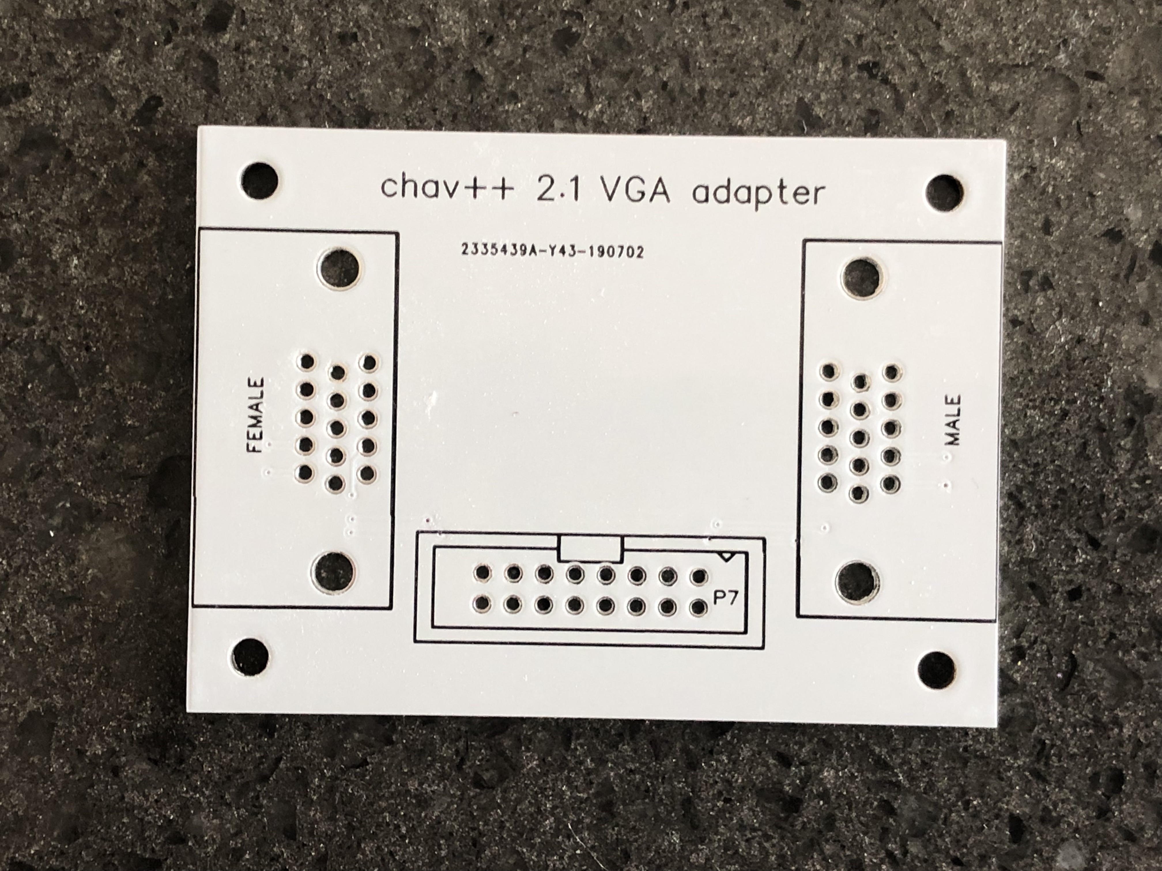
This is an option to order a bare PCB! You will have to source all other parts and build this yourself. Build docs are in our github.
This VGA adapter is how you interface your VGA signal provider with the ec500 system. By default, we use the same little red $5 VGA tester that Jonas used in the original CHA/V, but you can theoretically use anything else that outputs a VGA signal, up to & including your laptop, which I do not recommend, for the sole reason that I do not make any promises about this not damaging your laptop.
In essence, your VGA source plugs in to the right-hand side (w/the male pins), and your VGA display device plugs in to the left-hand side, and your ec500 error.core connects via the 16-pin ribbon cable in the center. That’s all there is to it. This adapter routes the necessary signals – R, G, B, hsync, vsync, ground – to the ec500, and then brings back whatever mangled RGB you generate with the ec500, sending it along to your display device.
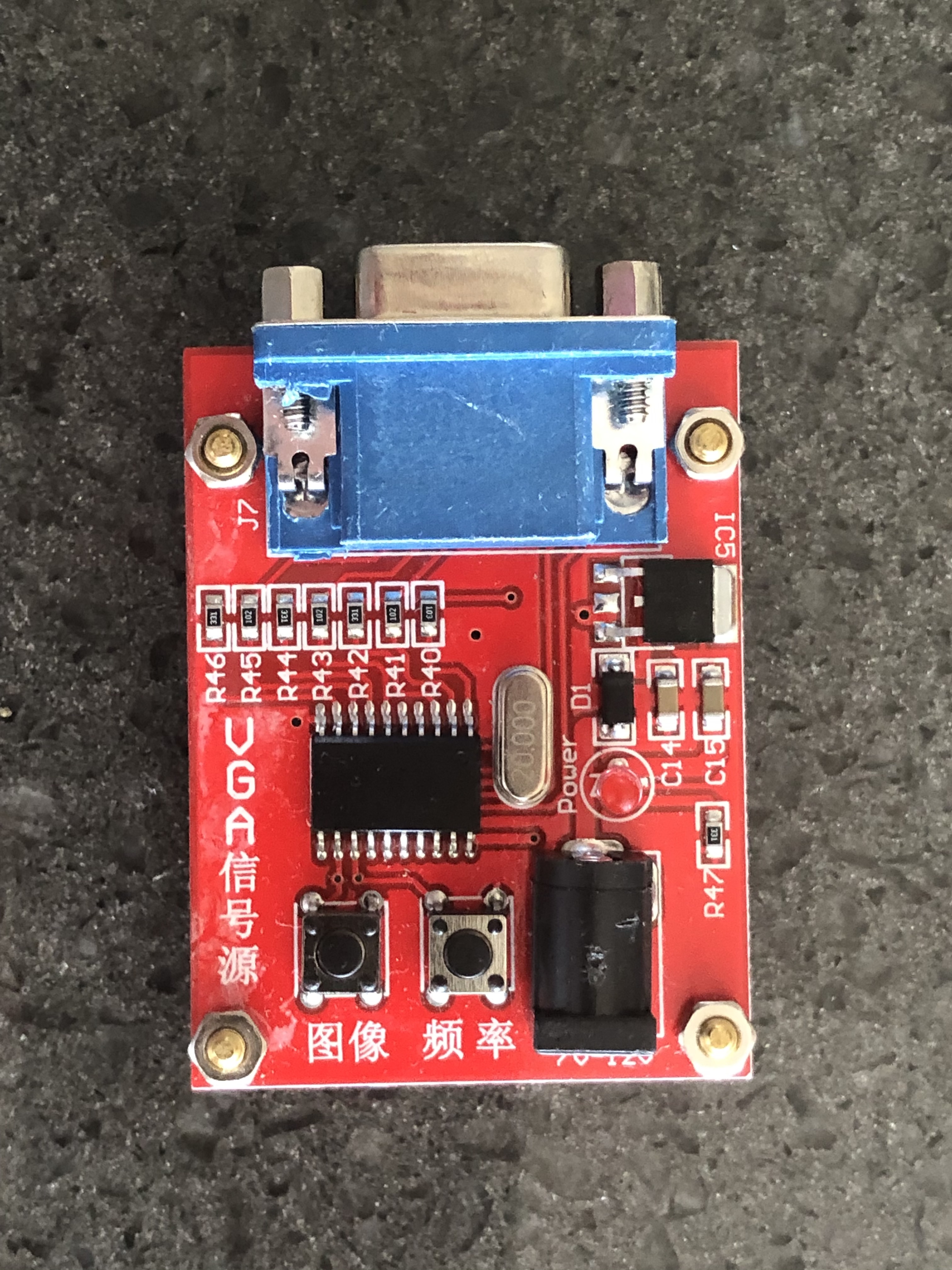
At the heart of Jonas Bers’s original CHA/V project was this absurdly cheap VGA tester available on eBay. As far as I know, it’s still available on eBay. We keep enough in stock to fulfill complete system orders, plus a couple of extras. You can order from us at a slightly higher price than you’ll find on eBay.

These are available any number of places. We recommend these because you get a decent assortment of lengths, and the ends are the molded types, which fit better into the headers on the ec500.
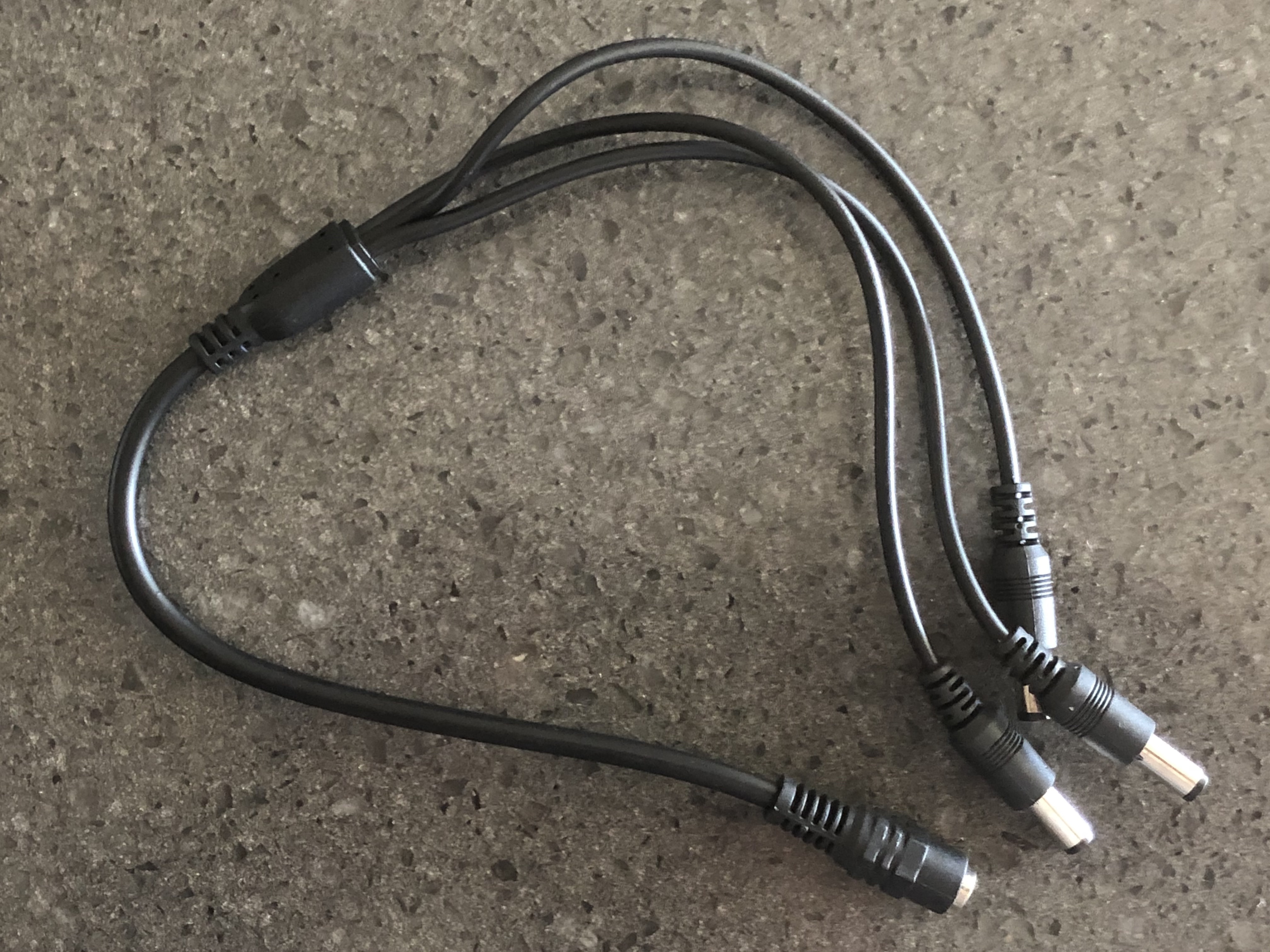
If you’re using the default ec500 configuration — at least an error.core, plus the cheap hacky red VGA tester — you’ll need 2 12V DC power supplies. Or one power supply and this handy splitter. Plus you get an extra unused end for free.
