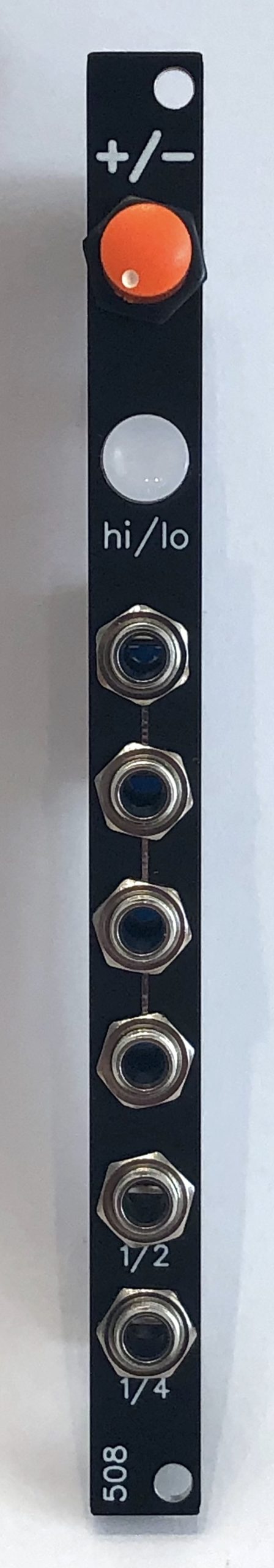
Range-switchable clock module that varies from ~1 Hz to ~12 Hz (actually down to 1/4 Hz thanks to the integral clock divider)
It has 4 outs of the main clock, plus 1 each of 1/2 and 1/4 clock division, designed to make it easy to do simple beats (or anything else requiring clock division) without needing a separate clock divider.
The pushbutton to change the range has a blinkenlight inside it.
This is for the PCBs and panel ONLY. This line of 2HP modules uses a few weird parts (the BOMs are posted on github) so if you aren’t confident in your ability to source everything, just order a kit.
Note that this is nearly entirely surface mount. I used to be scared of it but nowadays I prefer it to through-hole because you don’t wind up with all those little metal legs that fall on the floor & then get tracked into a room with carpeting where they stick up and stab you in the foot.
The six things you need for successful surface mount soldering at the scale of my kits (0805 size components):
- A decent soldering station
- A lighted magnifier
- Decent tweezers
- A flux pen
- .020″ solder
- If your iron is a Weller, an ETA tip, or the equivalent for your iron
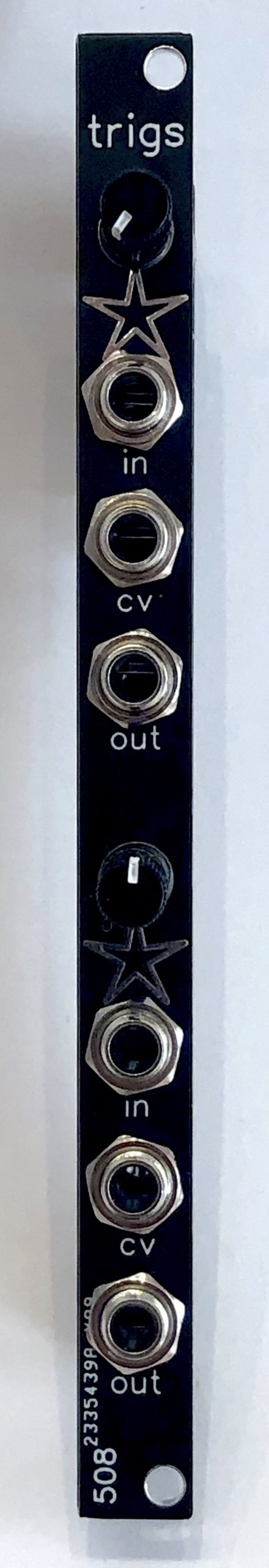
A lot of my percussion modules are expecting well-formed triggers, but clocks and other things typically put out gates. This is a dual gate-to-trigger conditioner — it will narrow just about any gate down to proper trigger width, but its output is also fully adjustable from 0ms up to the full width of the original gate. So you can use it if, for example, you’re using a clock divider that puts out double-length gates that you want to shape back down to the same width as the rest of the gates you’re using. Or anything else along those lines.
The trigger/gate width is fully CV controllable across the same range that the knob gives you.
The input of the top half is normalled to the input of the bottom half, in case you want 2 different lengths from the same gate input.
This is for the PCBs and panel ONLY. This line of 2HP modules uses a few weird parts (the BOMs are posted on github) so if you aren’t confident in your ability to source everything, just order a kit.
Note that this is nearly entirely surface mount. I used to be scared of it but nowadays I prefer it to through-hole because you don’t wind up with all those little metal legs that fall on the floor & then get tracked into a room with carpeting where they stick up and stab you in the foot.
The six things you need for successful surface mount soldering at the scale of my kits (0805 size components):
- A decent soldering station
- A lighted magnifier
- Decent tweezers
- A flux pen
- .020″ solder
- If your iron is a Weller, an ETA tip, or the equivalent for your iron
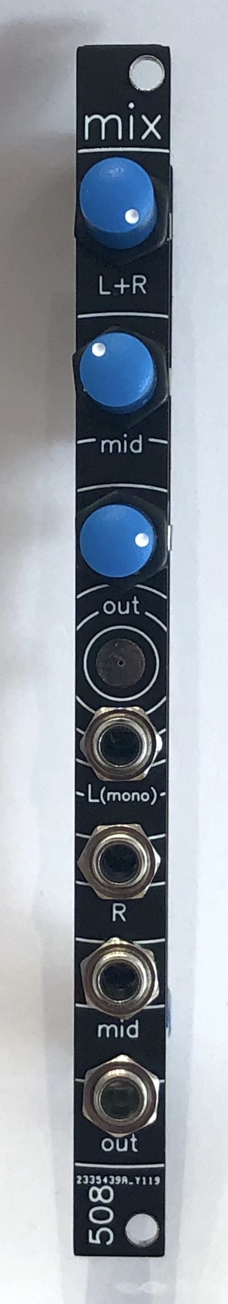
A simple stereo mixer — it has 1 plain-mono input, a second mono input that becomes a hard-panned left-channel when the third input, a dedicated right channel, is patched into. No pan pots, sorry, it’s 2HP. I actually designed it to go with a combination 4-way low-pass gate and stereo panning mixer that I haven’t gotten around to uploading here yet.
It has a reasonably decent headphone amplifier IC as its output stage, set to provide enough gain to drive my Sennheisers.
This is for the PCBs and panel ONLY. This line of 2HP modules uses a few weird parts (the BOMs are posted on github) so if you aren’t confident in your ability to source everything, just order a kit.
Note that this is nearly entirely surface mount. I used to be scared of it but nowadays I prefer it to through-hole because you don’t wind up with all those little metal legs that fall on the floor & then get tracked into a room with carpeting where they stick up and stab you in the foot.
The six things you need for successful surface mount soldering at the scale of my kits (0805 size components):
- A decent soldering station
- A lighted magnifier
- Decent tweezers
- A flux pen
- .020″ solder
- If your iron is a Weller, an ETA tip, or the equivalent for your iron

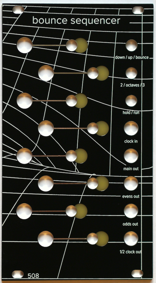
An 8-step sequencer with a playable (pushbuttons/toggle switches) interface. Toggle switch selects up / down / or bounce mode. In up or down mode, selecting any two switches will cause the sequencer to skip the steps between them (either between them on the inside, or between them on the outside, depending).
In bounce mode, any lit step will cause the sequencer to reverse direction when it hits it.
There’s a toggle to select ~2 octave or ~3 octave range, and a hold/run toggle.
In addition to the main clock input and the main sequence CV output, there are three additional outputs:
- CV from odd-numbered steps only
- CV from even-numbered steps only
- a one-half division of the clock
There is an expansion bus on the back for driving the optional 8-step trigger sequencer, and the optional variable gates module.
All build information — schematics, BOMs, etc — is on github: https://github.com/508-loop-detected/bounce-sequencer
An 8-step / 6 channel trigger sequencer with a pushbutton/toggle switch interface. Trigger width is controllable by the knobs, from a narrow trigger to a gate that can be . . . pretty wide. (a half-second? a second?)
The Trigger Sequencer WILL NOT DO ANYTHING without its sibling the Bounce Sequencer: https://508.loopdetected.net/product/bounce-sequencer-pcbpanel-pushbutton-version/
All of the actual logic is in the Bounce Sequencer, which connects via expansion bus on the back. THIS WILL NOT DO ANYTHING BY ITSELF
All information — schematics, BOM, etc — is on github: https://github.com/508-loop-detected/trigger-sequencer
An 8-step / 6 channel trigger sequencer with a pushbutton/toggle switch interface. Trigger width is controllable by the knobs, from a narrow trigger to a gate that can be . . . pretty wide. (a half-second? a second?)
The Trigger Sequencer WILL NOT DO ANYTHING without its sibling the Bounce Sequencer: https://508.loopdetected.net/product/bounce-sequencer-pcbpanel-toggles/
All of the actual logic is in the Bounce Sequencer, which connects via expansion bus on the back. THIS WILL NOT DO ANYTHING BY ITSELF
All information — schematics, BOM, etc — is on github: https://github.com/508-loop-detected/trigger-sequencer

This companion module to the Bounce Sequencer gives you individual control over both halves of the duty cycle of each step’s gate. The left-hand knob controls the high (the gate), and the right-hand knob controls the low (the time interval before the next gate fires). The button or toggle switch controls whether a gate is emitted at that step.
In externally-clocked mode, an external clock is plugged in to the Bounce Sequencer, and the sequence progresses based on that clock. Each gate will fire (or not, depending on the toggle) when the clock advances. It’s possible to set a gate length to span multiple clock steps in this mode.
In free-running mode, there is no clock plugged in to the Bounce Sequencer, and the Variable Gates module emits a clock step at the end of every gate cycle. This enables you to swing your sequence to the point of extreme stutter-step brokenness 🙂
The Variable Gates WILL NOT DO ANYTHING without its sibling the Bounce Sequencer: https://508.loopdetected.net/product/bounce-sequencer-pcbpanel-pushbutton-version/
All of the actual logic is in the Bounce Sequencer, which connects via expansion bus on the back.
Build info — schematics, BOMs, etc — is on github: https://github.com/508-loop-detected/variable-gates
This companion module to the Bounce Sequencer gives you individual control over both halves of the duty cycle of each step’s gate. The left-hand knob controls the high (the gate), and the right-hand knob controls the low (the time interval before the next gate fires). The button or toggle switch controls whether a gate is emitted at that step.
In externally-clocked mode, an external clock is plugged in to the Bounce Sequencer, and the sequence progresses based on that clock. Each gate will fire (or not, depending on the toggle) when the clock advances. It’s possible to set a gate length to span multiple clock steps in this mode.
In free-running mode, there is no clock plugged in to the Bounce Sequencer, and the Variable Gates module emits a clock step at the end of every gate cycle. This enables you to swing your sequence to the point of extreme stutter-step brokenness 🙂
The Variable Gates WILL NOT DO ANYTHING without its sibling the Bounce Sequencer: https://508.loopdetected.net/product/bounce-sequencer-pcbpanel-toggles/
All of the actual logic is in the Bounce Sequencer, which connects via expansion bus on the back.
Build info — schematics, BOMs, etc — is on github: https://github.com/508-loop-detected/variable-gates
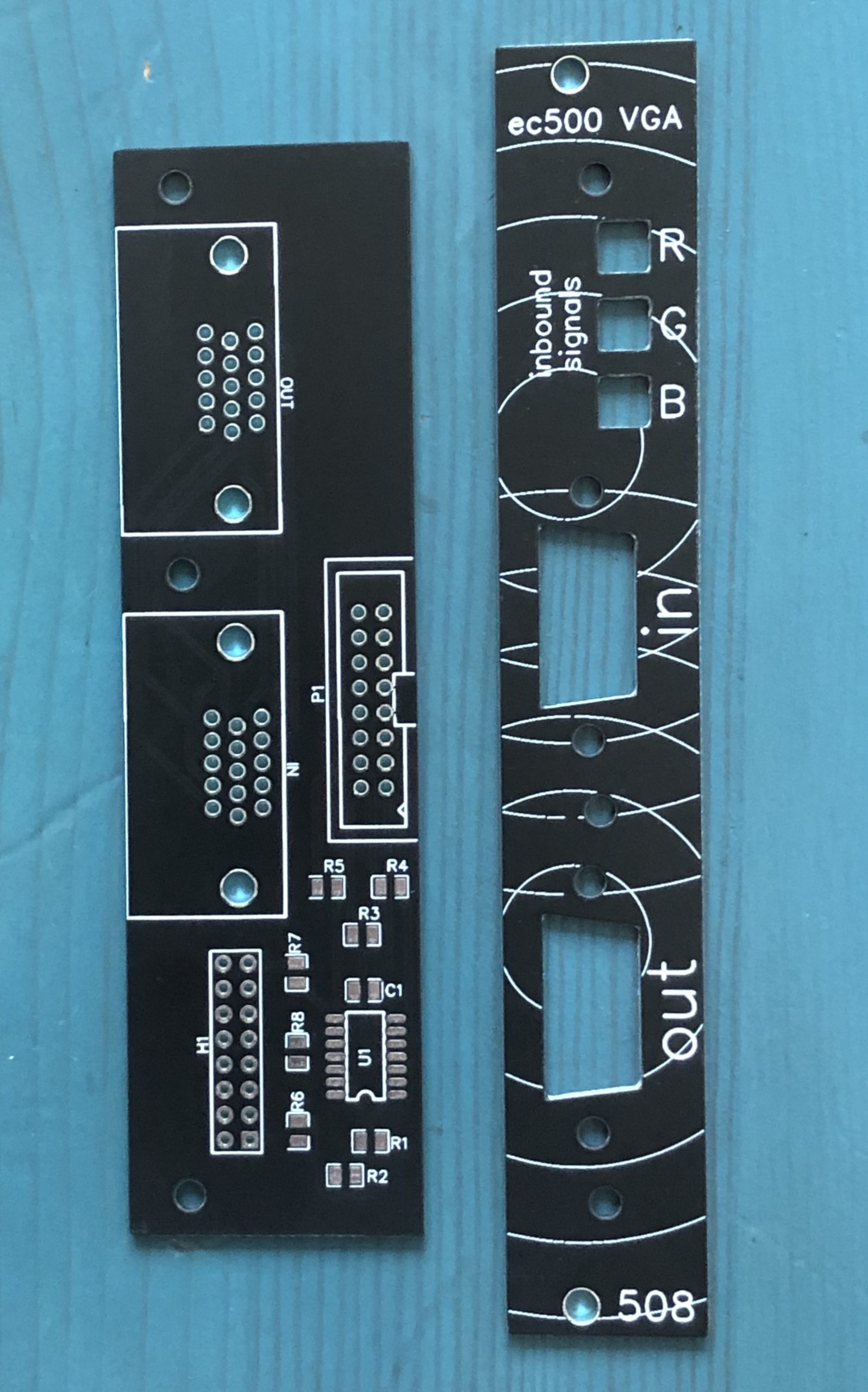
Updated VGA adapter designed for mounting in a 3U (e.g. Eurorack) enclosure. Also features buffered individual outputs for RGB coming in from your VGA input, for patching/processing in the ec500.
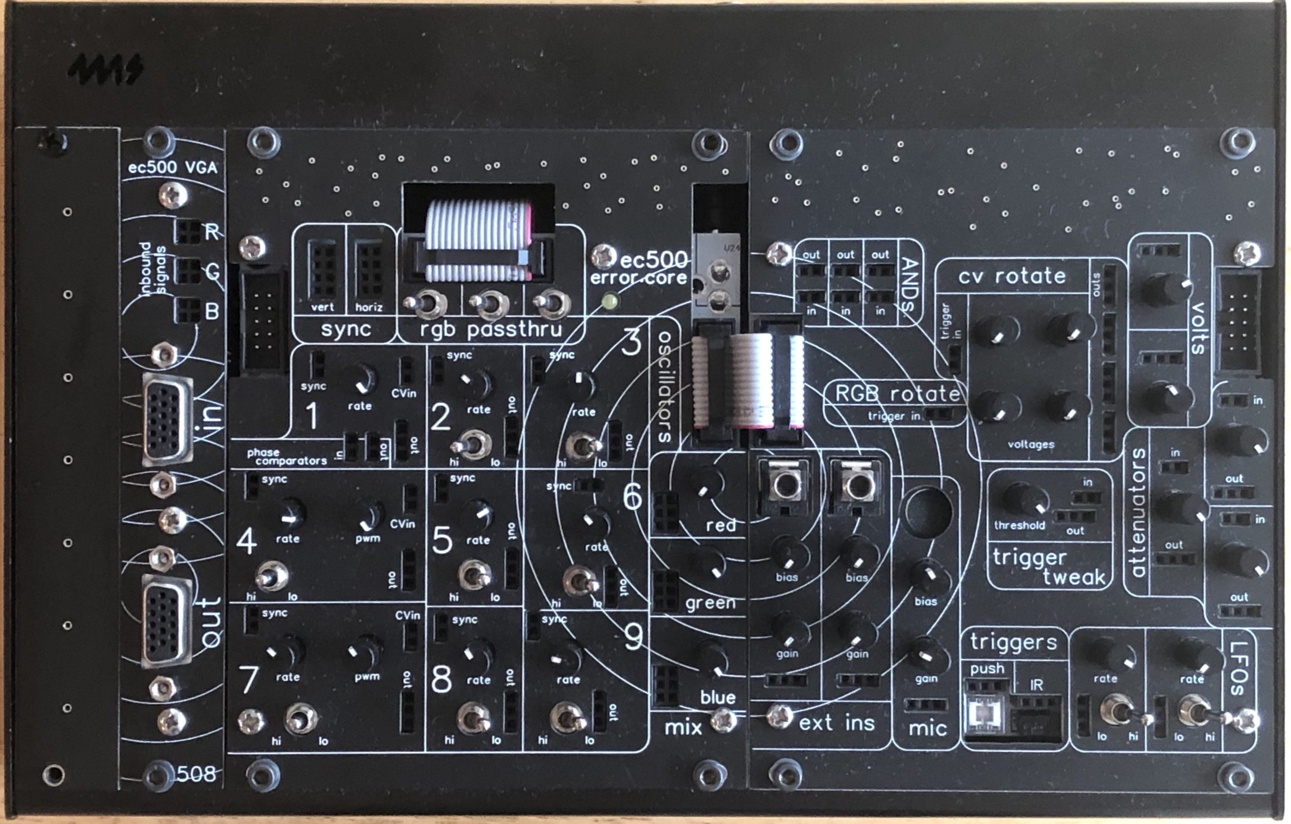
Here they are, the long-awaited 3U panels for the ec500 system. Mount your system in any enclosure that has 3U rails/spacing.
*note! These are front panels only! The system itself will fit into a 3U (i.e. Eurorack) case, but it’s still powered by a plain old 12V DC adapter.
Here they are, the long-awaited 3U panels for the ec500 system. Mount your system in any enclosure that has 3U rails/spacing.
*note! These are front panels only! The system itself will fit into a 3U (i.e. Eurorack) case, but it’s still powered by a plain old 12V DC adapter.
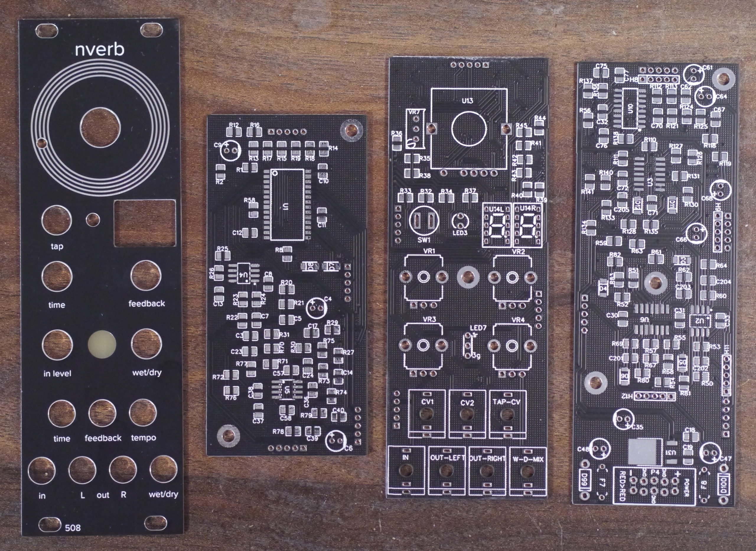
Reverb/Delay module based on the Nemesis NemFX reverb-on-a-chip (https://www.profusionplc.com/parts/nemfxsc-rdc1-so)
Main features:
- 16 programs
- 8 delays
- 2 choruses
- 2 spring reverbs
- 1 plate reverb
- 3 room/hall reverbs
- Tap Tempo (w/trigger CV input)
- CV control over time / feedback / wet-dry mix
- Mono in / Stereo out
8HP, 35mm deep, 140mA
Note: The NemFX chip is not recommended for new designs, i.e. it’s discontinued, but the distributor has them in stock as of this writing — check before trying to order boards or other parts!
Details at our github: https://github.com/508-loop-detected/nverb
